
Cobots in auto assembly require rigorously engineered safety, not hype. This post breaks down how standards like ISO 10218, ISO/TS 15066, and EN ISO 13849-1 drive collaborative cell design. We explore practical architectures for sensor fusion, real-time speed and separation monitoring (SSM), and functional safety implementation, showing how to validate and continuously audit safety systems to ensure robust human-robot collaboration on the factory floor.
Cobots in auto assembly are only viable when their safety behavior is engineered, validated, and monitored to the same standard as any other safety‑related control system in the plant. This article shows how ISO 10218 and EN ISO 13849 translate into concrete architectures for sensor fusion, real‑time decisioning, and auditability in collaborative auto assembly cells, and how these map onto the UK regulatory framework.
Modern assembly lines increasingly use Cobots for interior trim fitting, lightweight fastening, adhesive dispensing, and inspection, where humans and robots share space to meet takt time without full fencing. Cobots are attractive because they operate at lower forces, adapt to model variants, and reconfigure faster than traditional guarded cells, while still meeting machinery safety requirements when correctly engineered.
The 2025 revision of ISO 10218‑1 and ISO 10218‑2 integrates the collaborative application requirements previously covered in ISO/TS 15066, making it the main global reference for industrial and collaborative robot safety. ANSI/RIA R15.06 and CSA Z434 both adopt ISO 10218 as their technical basis, so aligning with it effectively covers North American requirements as well.
Implementing a collaborative assembly cell requires a layered approach to compliance. The following standards form the core framework for engineering and validating these systems:
ISO/TS 15066 (and now ISO 10218‑2) define four collaboration modes that can be combined within an auto assembly cell:
In auto assembly, typical patterns are PFL for slow collaborative screwing or clip‑in tasks close to the operator’s torso and arms, and SSM for larger motions such as door or hatch handling where higher speeds are needed while the human remains a short distance away. Combining SSM and PFL can improve productivity by allowing higher velocities at larger distances while guaranteeing safe contact behavior at close range, as demonstrated in research based on ISO/TS 15066 constraints.
A standards‑compliant cobot cell for auto assembly usually separates sensors into safety‑rated and non‑safety‑rated layers:
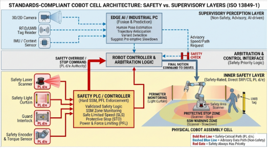
EN ISO 13849‑1 requires that any sensor contributing directly to a safety function be treated as part of an SRP/CS and evaluated for performance level, diagnostic coverage, and architecture category. Practically, that means only safety‑rated devices can be used to enforce protective stop, SSM, or safe limited speed, while non‑safety sensors may assist with prediction or early warning but cannot be the sole basis of a safety reaction.
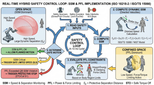
In SSM, ISO/TS 15066 and related implementation guidance compute a minimum protective separation distance as a function of human speed, robot speed, system reaction time, and position uncertainty. NIST and academic work on SSM highlight that ISO/TS 15066 uses directed speeds for the human and robot, so the algorithm must consider approach direction and braking time, not just scalar distance.
In practice, the SSM logic often ends up as a tight real‑time loop on a safety controller that reads distance, applies the ISO/TS 15066‑style protective distance calculation, and then clamps the robot’s commanded speed or issues a stop. The following (non‑certified) Python‑style pseudo‑code shows the structure of that safety filter; the actual implementation must reside in safety‑rated hardware/software and use validated parameters.
#Non-safety-rated illustrative pseudo-code ONLY.

#Real SSM/PFL must run in safety-rated HW/SW and be validated per ISO 10218 / EN ISO 13849-1.


from enum import Enum import time

class SafetyState

(Enum):

RUN = 1 # Full speed allowed

SLOW = 2 # Reduced speed

STOP = 3 # Safety-rated stop required


#Tuned from validation tests and ISO/TS 15066 / ISO 10218-2 calculations

HUMAN_MAX_SPEED = 1.6 # m/s, typical walking assumption[web:36][web:43]

ROBOT_MAX_SPEED = 1.0 # m/s, process-dependent

CONTROLLER_REACTION = 0.08 # s, sensor + logic + comms

POS_UNCERTAINTY = 0.10 # m, sensing and model error margin

FULL_SPEED_DIST = 2.0 # m, >= this: full speed allowed (example only)

SLOW_SPEED_DIST = 1.2 # m, between this and min distance: slow mode

MIN_PROTECT_DIST = 0.7 # m, <= this: must stop[web:19][web:35]


def min_protective_distance(v_h, v_r, t_react, c):

 """ ISO/TS 15066-style protective distance: S_p = v_h * t_react + v_r * t_react + c Here we fold braking margin into v_r and t_react for simplicity.[web:19][web:35] """

return v_h * t_react + v_r * t_react + c

def classify_state(current_distance: float) -> SafetyState:

# Always respect the theoretical minimum first

s_p = min_protective_distance(HUMAN_MAX_SPEED, ROBOT_MAX_SPEED, CONTROLLER_REACTION, POS_UNCERTAINTY)

 safety_limit = max(s_p, MIN_PROTECT_DIST)


if current_distance <= safety_limit:
    return SafetyState.STOP               # trigger safe stop
elif current_distance <= SLOW_SPEED_DIST:
    return SafetyState.SLOW               # clamp to reduced speed
else:
    return SafetyState.RUN                # full speed permitted


def safety_filter_loop(robot_iface, scanner_iface):

""" Runs inside the safety domain conceptually; here shown as normal code. robot_iface: abstraction to set safe speed / safe stop scanner_iface: abstraction to get min human-robot distance """


LOOP_TIME = 0.01 # 10 ms

while True:
    dist = scanner_iface.get_min_separation_distance()  # m

    state = classify_state(dist)

    if state == SafetyState.STOP:
        robot_iface.request_safe_stop()
    elif state == SafetyState.SLOW:
        robot_iface.set_safe_speed_limit(0.25 * ROBOT_MAX_SPEED)
    else:
        robot_iface.set_safe_speed_limit(ROBOT_MAX_SPEED)

    time.sleep(LOOP_TIME)
In a certified system, the same logic pattern is realised using safety‑rated scanners, a safety PLC or robot safety CPU, and validated reaction‑time and braking data, but the core idea - derive a minimum separation distance and clamp speed or stop based on it - remains the same.
1. Read safety sensors – scanner zones, gate interlocks, E‑stop chain, robot joint positions and velocities, enabling device status.
2. Compute separation distances in relevant directions and evaluate SSM constraints for each axis and potential human contact point.
3. Evaluate PFL constraints by checking that current or planned velocities and torques cannot produce forces above the allowable limits for the relevant body regions.
4. Determine safe motion – choose the most restrictive allowed velocity and direction or trigger a safety‑rated stop if no safe motion is possible.
Hybrid strategies that combine SSM and PFL can significantly improve throughput by letting the robot move faster at mid‑range distances (SSM‑dominated) while still respecting PFL limits during inevitable close contacts in tight workspaces. These algorithms still operate under strict limits defined by ISO/TS 15066 (now folded into ISO 10218‑2) and must be implemented within a functionally safe control path to be acceptable in production auto assembly.
EN ISO 13849‑1 defines how to design SRP/CS such that each safety function (for example, “perform safe stop on zone violation”) meets a target PLr derived from risk assessment. For collaborative auto assembly cells, many safety functions will target PL d or PL e, especially where injury severity is high or exposure is frequent.
The updated ISO 10218 emphasizes explicit functional safety requirements, introduces clearer classifications for robots based on their functional safety capabilities, and tightens test methods for maximum forces in collaborative operation. Cybersecurity aspects are also introduced, recognizing that manipulation of safety‑related communications can undermine functional safety if not protected.
Beyond design, standards require validation that implemented safety functions actually achieve the intended risk reduction under foreseeable operating conditions. ISO 10218‑2 and EN ISO 13849‑1 both expect validation to cover safety function performance, reaction to faults, and worst‑case parameter combinations.
For a cobot auto assembly cell, a robust validation campaign typically includes:
Because auto assembly involves frequent model changes and tooling swaps, engineering teams must define which configuration parameters are safety‑relevant (e.g., speed limits, scanner zones, collaborative workspace geometry) and require re‑validation when changed, and which are non‑safety process parameters that can be adjusted under change control without re‑running the full safety validation.
Standards like ISO 10218 and EN ISO 13849 focus on design and validation, but in production the burden shifts to continuous monitoring and auditability to demonstrate ongoing compliance and manage residual risk.
A robust auditability architecture typically includes:
A simple but effective pattern is to treat every safety function demand as an immutable, structured event written to a central log or message bus. Below is a minimal example that you can adapt to your plant’s logging stack (e.g. Kafka, Azure Event Hubs, Splunk, or an MES API).
#Non-safety logging example; structure is what matters for auditability.

import json

from datetime import datetime, timezone

from enum import Enum


class SafetyFunction(Enum):

ESTOP = "ESTOP"

GUARD_OPEN = "GUARD_OPEN"

SSM_VIOLATION = "SSM_VIOLATION"

PFL_EXCEEDED = "PFL_EXCEEDED"

STARTUP_CHECK = "STARTUP_CHECK"

def build_safety_event(

cell_id: str,

function: SafetyFunction,

severity: str,

details: dict,

operator_id: str | None = None,

):

event = {

"ts_utc": datetime.now(timezone.utc).isoformat(),

"cell_id": cell_id,

"function": function.value,

"severity": severity, # e.g. "INFO", "WARNING",

"CRITICAL"

"operator_id": operator_id,

"details": details,

# freeform; always JSON-serialisable }

return event

def write_event_to_bus(event: dict, producer):

""" 'producer' abstracts your bus/logger; could be Kafka producer, HTTP client, or a file writer. In production, add error handling and backpressure logic. """

payload = json.dumps(event)

producer.send("safety-events", payload.encode("utf-8"))

Example usage when SSM forces a stop:

def on_ssm_stop(cell_id, distance_m, limit_m, producer, operator_id=None):

evt = build_safety_event(

cell_id=cell_id,

function=SafetyFunction.SSM_VIOLATION,

severity="CRITICAL",

operator_id=operator_id,

details={

"measured_distance_m": distance_m,

"limit_distance_m": limit_m,

"robot_state": "MOVING",

},

)

write_event_to_bus(evt, producer)
EN ISO 13849‑1’s emphasis on predictable conditions and diagnostic coverage aligns with periodic proof tests and automated diagnostics scheduled and logged as part of plant maintenance. When AI‑based perception is used, its health indicators should be monitored, but system design must ensure that safety does not depend solely on non‑safety‑rated components.
In effect, a safe cobot cell in auto assembly is not a single clever algorithm but a stack of engineered safeguards: ISO 10218 defines what the robot and its integration must do, EN ISO 13849‑1 defines how the safety‑related control system must be structured and validated, and ISO/TS 15066 supplies the collaborative limits and modes that shape sensor fusion, real‑time decisioning, and PFL behaviour.
When you treat those standards as design inputs rather than paperwork, you end up with collaborative workstations where safety envelopes are explicit, enforceable in real time, and auditable over the life of the line: exactly what high‑mix, high‑volume auto assembly needs to collaborate with robots without accepting hidden risk.